Tuesday, June 15, 2010

The Lathe Bench

I didn't care for the stand my lathe was on. It was a skeleton made of angle iron. There was nowhere to place tools, no room for a chip tray, and it wobbled. I decided to build a proper bench.

This bench is about 19" x 72".

The surface is made of three sheets of 1/2" plywood, glued and screwed together, topped with a thin melamine-covered fiberboard sheet. The plywood wasn't the best choice but I already owned it - this material was stuff I had been tripping over in my shop.

The surface is resting on ten 2x4 'joists' spaced 8 inches on center. The joists are supported by 2x8 aprons. The 2x8s are bolted to 4x4 legs.

The ends are 3/4" plywood screwed and glued to the legs.

Here's an apron with it's joist hangers.


Because I could!


The other apron side is completed and the joists test-fitted.


Counter-bored holes for the lag screws. Note the flaw in the wood. I recommend you pay attention to these things.


Here a leg is attached to the apron. I clamped the leg against the apron, squared them, and bored two 1/4" holes through the apron into the leg. After that I opened the hole in the apron to 3/8" so the screw wouldn't split the wood. You can't really see it in these pictures but there's a washer below the lag screw heads.


The aprons and legs all together. The joists have also been attached to the hangers with a screw at each end. There's a good argument for putting a sheet of plywood under the apron to make sure it doesn't bow outward.


A great deal of the bench's strength comes from the plywood ends. I hate raw plywood edges. Invariably I ding them and raise a bunch of splinters. Then I impale myself. I covered up the top and front edges with a piece of 1/2" thick pine, glued and nailed.


I attached each plywood end piece to the legs using Liquid Nails and 44 screws. That's a lot of screws but they are functioning as clamps. Besides, I've had them for 15 years. Might as well use them. They are 'Robertson' screws from McFeely's. Highly recommended.


And here we are, both ends attached. The base of the bench is complete. If it shows any signs of lateral racking I'll add a piece of plywood or a diagonal support to the back.


My son and I dropped in the three 1/2" plywood top pieces, spreading Liquid Nails between them. I 'clamped' the plywood sheets together while the glue dried by driving 50 screws through them into the joists. I used some pretty old Philips-head deck screws for this. They cammed out terribly. I'm cured of Philips-head screws now.


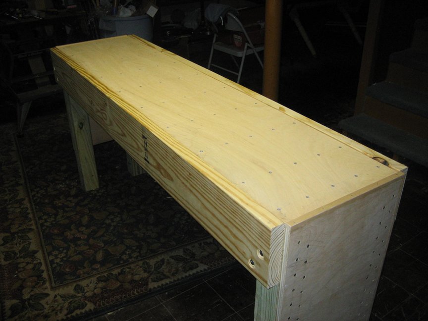
Screws. Yah. I could have used fewer. I'm glad I didn't.


I found a piece of fiberboard with melamine on one side. I used double-side tape to secure it to the bench. The fiberboard was leftover from another project. I was delighted to have enough, even if I did have to use two pieces.


And here's the lathe on its new bench. I haven't decided for sure where the lathe is going to sit.


And that's the bench. It's sturdy and economical. I spend about $70 on it, excluding the plywood top and fiberboard.

Sunday, June 13, 2010

The Powder Horn

Since I'm shooting black powder lately I thought I'd make a powder horn. Making a basic horn is pretty easy. Here's the cow horn I started with. It was was about 12" long:


The first step is to remove any 'scale', a loose covering, from the horn. I did this with a file. Then I cut the big end square so it could receive an end cap, cut the tip off, and bored the spout hole.


Already it isn't so gross :-) I assure you, it smelled like a cow.

I bored the spout to 1/4" using a standard twist drill bit. But the stopper will hold more securely if the hole is tapered, not straight sided. Being totally cheap, I wasn't about to buy a tapered reamer. Instead, I made one using from a piece of bar stock using a hacksaw and a few files. The taper is 1/16" over 1 1/4". I sawed a 5/16" wide finger in the bar stock then filed one edge so it tapered to 1/4" at the end. I selected one corner to be the cutting edge. I rounded the two opposite corners. Then I relieved the remaining corner so it wouldn't rub.

In this picture you can see the taper clearly. The shoulders at the wide end of the taper serve as a depth stop - when the shoulders touch the spout, the tapered hole is finished.


In the next picture, the geometry of the reamer is a little more evident. The 'rounded' corners on the right ride against the far side of the hole. The corner on the left top is the relieved edge. The remaining edge (left bottom) is the cutting edge.


I turned a cherry stopper on the lathe taking care to produce the same taper. Here's the stopper in the spout.


The next step was to fashion the end cap, a wooden plug glued into the end of the horn. Normally the large end is rounded using heat and a form. Then a round end cap fits very well. I opted to leave the horn in its natural shape pare the end cap to fit. Sometimes the end caps are inserted all the way into the horn. I wanted this end cap to protrude from the horn and overlap it's edges. I traced the large end of the horn onto a piece of 3/4" cherry then bandsawed the cap, adding some 'diameter' for the overlap I wanted.
I decided that 1/4" of the disk should remain outside the horn. To assure I had a clean shoulder to butt against the horn, I scribed a line around the circumference of the cap 1/4" from the 'outside' end. I sawed with a dovetail saw on the line all the way around to about 1/4" deep.

I pared the corners off the 'inside'-side of the blank so it would fit, if barely, into the horn. I rubbed a pencil lead on the inside of the horn to form a 'marking medium.' When I tried to insert the unshaped blank, it didn't go in far. The parts that rubbed on the inside of the horn picked up some graphite. This showed where the end cap was too large and prevented the end cap from seating properly. I pared off the graphite and a little wood underneath it then reinserted it. Now a different place rubbed and picked up some graphite. I pared that too. I repeated this fit/pare procedure until the lip I left on the end cap sat against flush against the end of the horn. This process, which is simple if tedious, eventually produces an end cap that fits beautifully.


After doing the fit/pare cycle about 100 times,... success.


Now horns are very thick at the pointy end. So thick, in fact, you can shape them easily using files, rasps, sandpaper, scrapers, etc. Powder horns frequently have a ring carved in them so they can be securely hung from a strap. I filed such a ring, then added flats to the spout to make a hexagon.


Once I was satisfied with the spout, I glued the end cap in. I used the entirely non-traditional Gorilla glue as it is waterproof and very strong. In addition, it expands when it cures hopefully plugging any gaps between the horn and the end cap. Common wood glue works too.

Once the glue cured I inserted 8 pegs around the circumference of the horn into the end cap. If the glue fails hopefully the pegs will prevent the end cap from popping off and dumping the powder onto the ground. Once the end cap was properly secured, I shaped it to my satisfaction using files, sandpaper, and steel wool. Then I carefully inserted a staple I made from a nail. I said previously that I carved a ring for one end of the carry strap. The staple holds the other end.

I think the perspective of the image is a little off - the staple isn't that large, lol.


A good going over with sand paper and steel wool finished the horn.


This was a very entertaining project. This horn is very spartan and is likely a fair representation of most 18th century horns. Most of these 'everyman' horns have been lost to time - there was no reason for people to save these relics. The next time I make a horn I'll try my hand at some more advanced carving and scrimshaw.

Thursday, June 10, 2010

The Dowel Jig

I am working on a project that requires a few cherry dowels around 3/4" long and 3/16" in diameter. I don't think I can get cherry dowels from the home center and I don't want to wait for an order to be shipped. I decided to build a dowel jig. It's nothing more than a steel plate with a series of holes (or dies) of decreasing diameter. The idea is that when the stock is driven through a die, any wood that doesn't fit will be trimmed away. Then the next smaller die is used, trimming down the stock a little more. This process is repeated until a dowel of the desired diameter is produced.

I started with this rough stock. These are cherry scraps about 1/4" x 1/4" at the largest.


I whittled the stock into a rough octagon then whittled a point on one end so it would fit in a die. Then I drove the stock through the dies in succession, starting with the largest which is 1/4". Here are the 3/16th dowels produced by driving the stock through the first 5 holes.


About half of my stock broke as I drove it through. This is because the grain wasn't straight or the wood had a flaw. The stock will break if there is any weakness so choose your stock carefully. Next time I'll use better wood and get a better result.

The largest hole in the jig above is 1/4" in diameter. The holes decease by 64ths to the smallest hole which is 1/8". I'd have to support the dowel stock somehow if I try to make a dowel smaller than 3/16".