Friday, October 26, 2012

The Electronic Quick Change Gear Box, part 5

(continued from part 4)

The block diagram from the previous entry may be informative but there's something to be said for seeing the actual components.

You can see the breaker box and VFD here, if you wish.  The breaker box is bog-standard. The VFD lives below in its own enclosure.  The control pendant (VFD Control in the block diagram) is sitting on the VFD enclosure. It has 2 toggles and a rotary knob.  One toggle powers the motor, another makes it run forward or reverse, and the knob sets motor's speed.  It's pretty sweet.  I'll be combining these controls with the new control panel.

Here's the power supply that will power the electronics and stepper motor:


It's somewhat over-sized being about 18" long.  It was salvaged from an industrial photocopier. This is great since it was made to power electronics and steppers.  It has 3.3v, 5v, and 24v outputs. It's basically perfect.  I am confident it will produce superb power and last for a long time.  And the price was right!

Here's the encoder. It came from U.S. Digital. It fills the palm of my hand.  The encoder consists of a case, a sensor fixed to the inside of the case, digital output pins, and disk that spins within the case.  The disk has 1024 marks on it.  As it spins, the marks pass through the sensor to produce pulses that are made available by the pins on the far right.  As an extra bonus, this particular encoder supports quadrature output which quadruples the number of pulses.  Thus this encoder produces 4096 pulses per revolution.  The lathe has a gear train connected to the spindle.  I'll mount the encoder to the head stock, fit a shaft to the hole in the encoder's disk, and spin the shaft from the gear train.


Here's the actual CPLD board I'll use for this project.  The image from part 1 of this series is a feature-rich development/learning board.  This board costs about 1/3 as much.  It measures just over 1" x 2".  It's a product of Dangerous Prototypes and sold by their partner seeedstudio.


Since I have not yet selected the stepper motor, I can't say for sure what stepper controller board I'll buy.  Candidates are the Big Easy Driver from Sparkfun and Polulu's A4988 Stepper Motor Driver Carrier with Voltage Regulators.

The stepper will be standard. Right now I'm debating on the NEMA 23 or 34 frame size.  I'm leaning towards a bipolar model with a 23 frame and 1.8 degree steps.  The torque is really the question now.

Sunday, October 21, 2012

The Electronic Quick Change Gear Box, part 4

(continued from part 3)

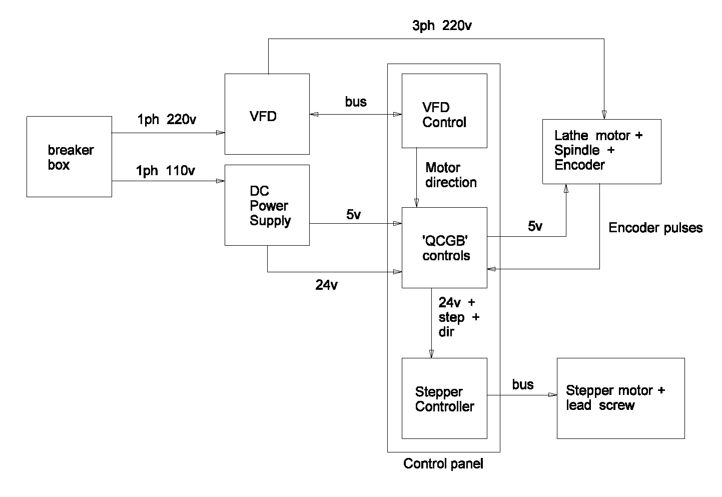
Continuing on, it will be helpful at this time to identify the physical components of the lathe and QCGB components.  It always surprises me how many parts there are when I take a step back.

Working roughly from left to right, we have:

1. The breaker box.  This is typical and has 220v 1ph power running to it.  Here's a picture including the VFD.  It will supply 220v power to the VFD and 110 to the DC Power Supply.

2. VFD. This is a remarkable device that converts garden-variety one-phase power into three-phase power. The VFD also affords a remarkable amount of control over many aspects the motor. Highly recommended.  The VFD is controlled by the 'VFD Control' component, which I'll get to soon.

3. DC Power Supply.  The stepper motor needs 24v at up to 2 amps.  The CPLD requires 5 volts and a few milliamps of power.  The DC power supply will produce both from wall current.

4. VFD Control:  These are remote controls for the VFD. They allow me turn on the motor, control the speed, and control the motor's direction or rotation.  The only commonality between these controls and the QCGB project is that I want to know the direction the motor is spinning.  This is crucial when cutting metric threads.

5. 'QCGB' controls:  These are the controls specifically dealing with the QCGB and the circuitry to support them.  You can see a diagram of what they may look like the previous installment of this blog.  The controls include some indicator LEDs and a switch that energizes the CPLD and the stepper controller.  What's important here is that the 24v stepper power be isolated from the 5v general electronics circuitry.  This will likely be done with a relay.  The CPLD that's under the hood is is the heart of the project.  It collects the pulses from the spindle, performs the division, and sends the result to the stepper controller.

6. Stepper controller:  This is a circuit that accepts a pulse and direction and moves the stepper motor appropriately. It does this by manipulating the motor's windings using the 24v 2a power supplied by the DC power supply.

7.Stepper Motor and lead screw: The stepper motor is a motor designed to rotate in discreet steps, with 200 steps/rev being common. They allow very fine control. As the stepper motor turns, it turns the lead screw and this pulls the carriage down the lathe and a very controlled speed.

8. Lathe motor, spindle, and encoder.  The motor spins the spindle which spins the encoder.  The encoder I'm using will produce 4096 pulses every time the spindle makes one complete revolution.  These pulses are fed into the CPLD chip which is configured to divide in such a way to send the proper number of pulses to the stepper controller.

The VFD Control, 'QCGB' controls, Stepper Controller, and related controls will be housed in a metal case and be presented to the user by a control panel.

The VFD is already housed in the breaker box.

Part 5 is Right This Way...

Friday, October 5, 2012

The Electronic Quick Change Gear Box, part 3

(continued from part 2)

The Control Panel

Refer back to part 1 of this series to see pictures of a real quick change gearbox.  My electronic version will be similar.

The circuit boards and switches will be contained in a box that's perhaps 10" x 5" x 2".

The real QCGB has two levers on the bottom.  I'll use rotary switches.  I recently purchased two mil-spec 8-position switches for this project.  They're excellent.  I was originally going to use 10-position switches but it turned out that 8 positions are plenty.  These two switches will yield 64 threads and feeds.

Here's a sample of what the control panel might look like.


The chart on the left tells the operator how to set the two 8-position rotary switches.  The chart itself has three sections; rows A-D are for standard threads.  For example, the "10" in that section of the table means 10 threads per inch.  Rows E and F are for feeds.  They may be thought of as very fine threads.  The tool used for feeds will be purposefully ground so as to obliterate any thread artifacts.  Rows G and H are for metric thread pitches, in millimeters.

The two circles below represent the 8 position rotary switches mentioned earlier. The switch on the left selects the row and the switch on the right selects the column.  For example, if you want a 13 TPI thread, you'd find 13 in the upper 4 rows, then set the switches to B-6.

Small circles represent 10mm LEDs.  The column of 4 LEDs to the center-right tell the operator how the selected thread relates to the lathe's threading dial.  Most of the time the "choose any mark or number" LED will be lit.  If cutting metric threads, the "Do Not Disengage" LED will be lit.  A few oddball threads will cause one of the other LEDs to be lit.

The rectangle below these LEDs (and the other similar rectangles) represents a toggle switch.  This one supplies power to the electronics and the stepper motor.

Finally, moving to the rightmost column includes controls that have nothing to do with the QCGB but are included since they must all work together ergonomically.  The toggle on the bottom causes the lathe's motor to start running.  The circle above that is a knob that controls the speed of the motor.  The toggle on the top determines the direction the motor spins.

I expect to mount the control panel on the left end of the lathe making the power switch the most easily accessed control.  Seems prudent.

Part 4 continues here...