More about the CPLD
I've said that the CPLD doesn't run a program, yet I talk about programming it. How is this not double-speak?
The distinction is that a program can be thought of a series of instructions executed by some manner of processor such as an Arduino. When the processor is started, the program might be loaded from eprom into volatile memory and the processor's instruction pointer set to the appropriate location. The program runs, the sun shines, and the birds sing.
But for the CPLD, things are different. When I talk about programming it, I'm not talking about creating a sequence of instructions. Instead, I'm talking about configuring connections between gates that are baked into the CPLD's silicon.
Verilog
Connecting wires to IC pins is very tedious. While it would be possible to virtually solder the connections between the CPLD's gates, developers needed something a more efficient and less error-prone way. Verilog was thus created. It's a language having elements that should be familiar to almost all programmers. It includes support for primitive constructs but also support for building and reusing higher level constructs. The web is full of references and Amazon sells many books about Verilog. Just for a taste, the following is a perfectly valid Verilog program that makes one of the LEDs on my development board flash every second.
01 module demodelay(
02 input CLK,
03 output reg GO
04 );
05
06 reg[18:0] snooze = 0;
07 always @(posedge CLK) begin
08 snooze = snooze + 1;
09 if (snooze == 500000) begin
10 GO = !GO;
11 snooze = 0;
12 end
13 end
14 endmodule
This isn't so different looking from a normal C or Java program. Same stuff, different syntax. Here are the high points. (Bear in mind, this Verilog module is written so it's easy to explain and understand and does not take advantage of knowledge about what we're really doing, which is configuring hardware. This module could be written far more efficiently.)
On line 1, we see the name of the module is declared - demodelay.
On line 2, we see the input is something called CLK. The program has a configuration that ties a 1MHz clock signal to this input. Thus CLK will transition from low to high 1 million times a second.
On line 3, the output is something called GO. This is what will drive the LED output. Note the word 'reg'. This makes the value persistent. Once we set the value, it stays that way.
Line 6 shows something that looks like a variable. It is, after a fashion. It's 19 bits of persistent storage. Every one of these bits will become a flip-flop or a latch. So here's one difference between Verilog and typical programming languages - In Verilog, we care very much how wide our variables are - these definitions contribute directly to the consumption of the CPLD's resources. If we were programming in Java, we might just declare 'snooze' to be an int. When our method was invoked, the JVM would create a stack frame including 32 bits of storage for 'snooze'. When our method exited, the JVM would reclaim the stack frame. We wouldn't worry too much about the underlying reality; this is the point of using higher level languages.
Magic begins on line 7. What this statement means is that whenever CLK (an input) transitions from a low state to a high state (0 to 3.3v, perhaps), the logic represented by the code within the begin and matching end (line 13) will be made active. I said that in a peculiar fashion because no code is being 'executed', for this does not exist for a CPLD.
So, once we see the CLK signal transition to high, line 8 increments our 'snooze' variable. What does this mean? It means that the least significant flip-flop in the 19 flip-flops represented by 'snooze' will be toggled, and this may cause carries to ripple up the other flip-flops. Because the CLK signal is transitioning a million times a second, we're incrementing the snooze register one million times a second.
Remember, the whole point of the module is to make the LED blink. This begins to happen with line 9. If the value of our register is 500,000, additional logic should be enabled - the logic between lines 9 and 12. Since we're using a 1Mhz clock, 500,000 counts represents one half of a second. This enormous division is required to convert machine-speed into human-speed.
Line 10 shows that our output variable, GO, is inverted. So if it's 1, the value becomes 0, and vice-versa. Note that on line 3 we declared GO as 'reg'. This means that, like our 'snooze' counter, GO is persistent; it will retain its value. Practically speaking the LED attached to GO will stay off or on for 1/2 of a second.
Finally, on line 11, we reset the 'snooze' counter so the process repeats every half a second - we toggle GO off and on, endlessly.
If this were implemented in a high level language, this would be a series of machine instructions. We all get that. However, since Verilog configures hardware, the human-consumable output is a schematic, of sorts. Here's a section of the output relating to the comparison to 500,000:
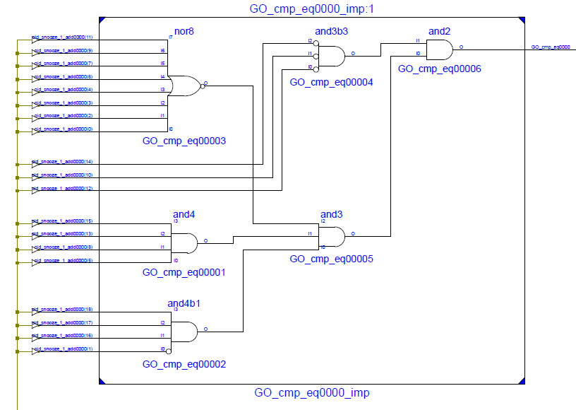
Here's another snippet showing the least significant 4 bits of the adder produced by line 8 of the Verilog above:

The full schematic is too large to reproduce here. It's safe to assume, however, it includes perhaps 120 gates.
I entered the Verilog above into the ISE design package provided by Xilinx. ISE is an easy-to-use software package that includes a Verilog compiler and the related tools. It produces a binary that can be sent to the CPLD using a JTAG or USB interface. I use Digilent's 'Coolrunner II Utility Window' software to write the binary to the CPLD. It's easy and takes about 5 seconds. Once the writing finishes, the board resets and the new configuration begins running. Right now the development board is flashing at me dutifully.
In summary, we've learned that Verilog is a common language for configuring CPLDs. In its simplest form it's very familiar to most programmers. We've also seen that Verilog produces not executable code, but a gate-level representation suitable for implementation at the hardware level. Finally, we learned that the gate-level implementation is written to the the CPLD is using a USB or JTAG interface.
End of part 2.
In part 3, I'll discuss the control panel. This will make it easier to understand where this is going.