Friday, October 26, 2012

The Electronic Quick Change Gear Box, part 5

(continued from part 4)

The block diagram from the previous entry may be informative but there's something to be said for seeing the actual components.

You can see the breaker box and VFD here, if you wish.  The breaker box is bog-standard. The VFD lives below in its own enclosure.  The control pendant (VFD Control in the block diagram) is sitting on the VFD enclosure. It has 2 toggles and a rotary knob.  One toggle powers the motor, another makes it run forward or reverse, and the knob sets motor's speed.  It's pretty sweet.  I'll be combining these controls with the new control panel.

Here's the power supply that will power the electronics and stepper motor:


It's somewhat over-sized being about 18" long.  It was salvaged from an industrial photocopier. This is great since it was made to power electronics and steppers.  It has 3.3v, 5v, and 24v outputs. It's basically perfect.  I am confident it will produce superb power and last for a long time.  And the price was right!

Here's the encoder. It came from U.S. Digital. It fills the palm of my hand.  The encoder consists of a case, a sensor fixed to the inside of the case, digital output pins, and disk that spins within the case.  The disk has 1024 marks on it.  As it spins, the marks pass through the sensor to produce pulses that are made available by the pins on the far right.  As an extra bonus, this particular encoder supports quadrature output which quadruples the number of pulses.  Thus this encoder produces 4096 pulses per revolution.  The lathe has a gear train connected to the spindle.  I'll mount the encoder to the head stock, fit a shaft to the hole in the encoder's disk, and spin the shaft from the gear train.


Here's the actual CPLD board I'll use for this project.  The image from part 1 of this series is a feature-rich development/learning board.  This board costs about 1/3 as much.  It measures just over 1" x 2".  It's a product of Dangerous Prototypes and sold by their partner seeedstudio.


Since I have not yet selected the stepper motor, I can't say for sure what stepper controller board I'll buy.  Candidates are the Big Easy Driver from Sparkfun and Polulu's A4988 Stepper Motor Driver Carrier with Voltage Regulators.

The stepper will be standard. Right now I'm debating on the NEMA 23 or 34 frame size.  I'm leaning towards a bipolar model with a 23 frame and 1.8 degree steps.  The torque is really the question now.

Sunday, October 21, 2012

The Electronic Quick Change Gear Box, part 4

(continued from part 3)

Continuing on, it will be helpful at this time to identify the physical components of the lathe and QCGB components.  It always surprises me how many parts there are when I take a step back.

Working roughly from left to right, we have:

1. The breaker box.  This is typical and has 220v 1ph power running to it.  Here's a picture including the VFD.  It will supply 220v power to the VFD and 110 to the DC Power Supply.

2. VFD. This is a remarkable device that converts garden-variety one-phase power into three-phase power. The VFD also affords a remarkable amount of control over many aspects the motor. Highly recommended.  The VFD is controlled by the 'VFD Control' component, which I'll get to soon.

3. DC Power Supply.  The stepper motor needs 24v at up to 2 amps.  The CPLD requires 5 volts and a few milliamps of power.  The DC power supply will produce both from wall current.

4. VFD Control:  These are remote controls for the VFD. They allow me turn on the motor, control the speed, and control the motor's direction or rotation.  The only commonality between these controls and the QCGB project is that I want to know the direction the motor is spinning.  This is crucial when cutting metric threads.

5. 'QCGB' controls:  These are the controls specifically dealing with the QCGB and the circuitry to support them.  You can see a diagram of what they may look like the previous installment of this blog.  The controls include some indicator LEDs and a switch that energizes the CPLD and the stepper controller.  What's important here is that the 24v stepper power be isolated from the 5v general electronics circuitry.  This will likely be done with a relay.  The CPLD that's under the hood is is the heart of the project.  It collects the pulses from the spindle, performs the division, and sends the result to the stepper controller.

6. Stepper controller:  This is a circuit that accepts a pulse and direction and moves the stepper motor appropriately. It does this by manipulating the motor's windings using the 24v 2a power supplied by the DC power supply.

7.Stepper Motor and lead screw: The stepper motor is a motor designed to rotate in discreet steps, with 200 steps/rev being common. They allow very fine control. As the stepper motor turns, it turns the lead screw and this pulls the carriage down the lathe and a very controlled speed.

8. Lathe motor, spindle, and encoder.  The motor spins the spindle which spins the encoder.  The encoder I'm using will produce 4096 pulses every time the spindle makes one complete revolution.  These pulses are fed into the CPLD chip which is configured to divide in such a way to send the proper number of pulses to the stepper controller.

The VFD Control, 'QCGB' controls, Stepper Controller, and related controls will be housed in a metal case and be presented to the user by a control panel.

The VFD is already housed in the breaker box.

Part 5 is Right This Way...

Friday, October 5, 2012

The Electronic Quick Change Gear Box, part 3

(continued from part 2)

The Control Panel

Refer back to part 1 of this series to see pictures of a real quick change gearbox.  My electronic version will be similar.

The circuit boards and switches will be contained in a box that's perhaps 10" x 5" x 2".

The real QCGB has two levers on the bottom.  I'll use rotary switches.  I recently purchased two mil-spec 8-position switches for this project.  They're excellent.  I was originally going to use 10-position switches but it turned out that 8 positions are plenty.  These two switches will yield 64 threads and feeds.

Here's a sample of what the control panel might look like.


The chart on the left tells the operator how to set the two 8-position rotary switches.  The chart itself has three sections; rows A-D are for standard threads.  For example, the "10" in that section of the table means 10 threads per inch.  Rows E and F are for feeds.  They may be thought of as very fine threads.  The tool used for feeds will be purposefully ground so as to obliterate any thread artifacts.  Rows G and H are for metric thread pitches, in millimeters.

The two circles below represent the 8 position rotary switches mentioned earlier. The switch on the left selects the row and the switch on the right selects the column.  For example, if you want a 13 TPI thread, you'd find 13 in the upper 4 rows, then set the switches to B-6.

Small circles represent 10mm LEDs.  The column of 4 LEDs to the center-right tell the operator how the selected thread relates to the lathe's threading dial.  Most of the time the "choose any mark or number" LED will be lit.  If cutting metric threads, the "Do Not Disengage" LED will be lit.  A few oddball threads will cause one of the other LEDs to be lit.

The rectangle below these LEDs (and the other similar rectangles) represents a toggle switch.  This one supplies power to the electronics and the stepper motor.

Finally, moving to the rightmost column includes controls that have nothing to do with the QCGB but are included since they must all work together ergonomically.  The toggle on the bottom causes the lathe's motor to start running.  The circle above that is a knob that controls the speed of the motor.  The toggle on the top determines the direction the motor spins.

I expect to mount the control panel on the left end of the lathe making the power switch the most easily accessed control.  Seems prudent.

Part 4 continues here...


Sunday, September 30, 2012

The Electronic Quick Change Gear Box, part 2

(continued from part 1)

More about the CPLD

I've said that the CPLD doesn't run a program, yet I talk about programming it.  How is this not double-speak?

The distinction is that a program can be thought of a series of instructions executed by some manner of processor such as an Arduino.  When the processor is started, the program might be loaded from eprom into volatile memory and the processor's instruction pointer set to the appropriate location.  The program runs, the sun shines, and the birds sing.

But for the CPLD, things are different. When I talk about programming it, I'm not talking about creating a sequence of instructions.  Instead, I'm talking about configuring connections between gates that are baked into the CPLD's silicon.

Verilog

Connecting wires to IC pins is very tedious.  While it would be possible to virtually solder the connections between the CPLD's gates, developers needed something a more efficient and less error-prone way.  Verilog was thus created.  It's a language having elements that should be familiar to almost all programmers.  It includes support for primitive constructs but also support for building and reusing higher level constructs. The web is full of references and Amazon sells many books about Verilog.  Just for a taste, the following is a perfectly valid Verilog program that makes one of the LEDs on my development board flash every second.


01 module demodelay(
02    input CLK,
03    output reg GO
04    );
05
06    reg[18:0] snooze = 0;
07    always @(posedge CLK) begin
08        snooze = snooze + 1;
09        if (snooze == 500000) begin
10            GO = !GO;
11            snooze = 0;
12            end
13        end
14 endmodule

This isn't so different looking from a normal C or Java program.  Same stuff, different syntax.  Here are the high points.  (Bear in mind, this Verilog module is written so it's easy to explain and understand and does not take advantage of knowledge about what we're really doing, which is configuring hardware.  This module could be written far more efficiently.)

On line 1, we see the name of the module is declared - demodelay.

On line 2, we see the input is something called CLK.  The program has a configuration that ties a 1MHz clock signal to this input.  Thus CLK will transition from low to high 1 million times a second.

On line 3, the output is something called GO.  This is what will drive the LED output.  Note the word 'reg'.  This makes the value persistent.  Once we set the value, it stays that way.

Line 6 shows something that looks like a variable.  It is, after a fashion.  It's 19 bits of persistent storage. Every one of these bits will become a flip-flop or a latch. So here's one difference between Verilog and typical programming languages - In Verilog, we care very much how wide our variables are - these definitions contribute directly to the consumption of the CPLD's resources.  If we were programming in Java, we might just declare 'snooze' to be an int.  When our method was invoked, the JVM would create a stack frame including 32 bits of storage for 'snooze'.  When our method exited, the JVM would reclaim the stack frame.  We wouldn't worry too much about the underlying reality; this is the point of using higher level languages.

Magic begins on line 7.  What this statement means is that whenever CLK (an input) transitions from a low state to a high state (0 to 3.3v, perhaps), the logic represented by the code within the begin and matching end (line 13) will be made active.  I said that in a peculiar fashion because no code is being 'executed', for this does not exist for a CPLD.

So, once we see the CLK signal transition to high, line 8 increments our 'snooze' variable. What does this mean?  It means that the least significant flip-flop in the 19 flip-flops represented by 'snooze' will be toggled, and this may cause carries to ripple up the other flip-flops. Because the CLK signal is transitioning a million times a second, we're incrementing the snooze register one million times a second.

Remember, the whole point of the module is to make the LED blink.  This begins to happen with line 9.  If the value of our register is 500,000,  additional logic should be enabled - the logic between lines 9 and 12.  Since we're using a 1Mhz clock, 500,000 counts represents one half of a second.  This enormous division is required to convert machine-speed into human-speed.

Line 10 shows that our output variable, GO, is inverted.  So if it's 1, the value becomes 0, and vice-versa.  Note that on line 3 we declared GO as 'reg'. This means that, like our 'snooze' counter, GO is persistent; it will retain its value.  Practically speaking the LED attached to GO will stay off or on for 1/2 of a second.

Finally, on line 11, we reset the 'snooze' counter so the process repeats every half a second - we toggle GO off and on, endlessly.

If this were implemented in a high level language, this would be a series of machine instructions.  We all get that.  However, since Verilog configures hardware, the human-consumable output is a schematic, of sorts.  Here's a section of the output relating to the comparison to 500,000:


Here's another snippet showing the least significant 4 bits of the adder produced by line 8 of the Verilog above:


The full schematic is too large to reproduce here.  It's safe to assume, however, it includes perhaps 120 gates.

I entered the Verilog above into the ISE design package provided by Xilinx.  ISE is an easy-to-use software package that includes a Verilog compiler and the related tools.  It produces a binary that can be sent to the CPLD using a JTAG or USB interface.  I use Digilent's 'Coolrunner II Utility Window' software to write the binary to the CPLD.  It's easy and takes about 5 seconds.  Once the writing finishes, the board resets and the new configuration begins running.  Right now the development board is flashing at me dutifully.

In summary, we've learned that Verilog is a common language for configuring CPLDs.  In its simplest form it's very familiar to most programmers.  We've also seen that Verilog produces not executable code, but a gate-level representation suitable for implementation at the hardware level. Finally, we learned that the gate-level implementation is written to the the CPLD is using a USB or JTAG interface.

End of part 2.

In part 3, I'll discuss the control panel.  This will make it easier to understand where this is going.


Wednesday, September 26, 2012

The Electronic Quick Change Gear Box, Part 1

I've posted about my adventures with restoring my 1937 Craftsman 12" lathe.  Today I'll begin something a little different - I'll post about creating an accessory for this lathe to simulate a quick change gearbox (henceforth, QCGB.)

To understand what I am doing, you have to know some basics of lathes.  I'll refer you to Tubalcain, a well regarded instructor. Listen carefully for 'quick change gear box' and 'lead screw.'

One of the neatest capabilities of a lathe is the ability to cut screw threads.  Here's a link to a classic video showing this in action:

Cutting threads

(In that video, the camera is mounted to the carriage.  It looks like the work is moving. It isn't.  The carriage is moving.)

We saw how the lathe cut a screw thread.  But that didn't happen by itself.  What made the cutter find just the right spot to begin?  Why did it cut that rather coarse thread instead of a fine thread?  Why did it cut a thread at all, and not produce a cylinder?

The reason is that the operator configured the lathe so the spindle was connected to the lead screw using a carefully selected gear train. The gear train controlled the ratio of spindle turns to lead screw turns, and by extension the the ratio of spindle revolutions to carriage movement.  If the spindle makes 20 revolutions and the carriage moves 1", a 20 TPI thread will be produced.

In the old days, the ratio between the spindle and lead screw was set by elaborate combinations of individual change gears.  In this picture, the four gears at the bottom (look sharp to see the 4th!) are the change gears.  Those gears were selected from a stack of gears, according to a chart, in order to produce the desired ratio.


So, it takes time to get those gears set up.  Every time you want to move the carriage at a different rate, you need a different change gear setup.

Enter the QCGB

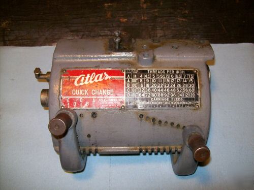
Someone enterprising person realized that if the gears could be engaged as needed, machinists would save a lot of time and thus be more profitable.  The result was the quick change gear box.  While there are many designs and these have evolved over the last century, this QCGB from the Atlas company is representative:


It's simple to use.  We see two levers and a chart.  If you want to cut a certain thread, first find the TPI in the chart.  Note the letter on the left edge of the chart. The left lever is set to the position corresponding to this letter.  Then the right lever is aligned with the column including the desired TPI. That's it. For example, if you wanted to cut a 20 TPI thread, you'd set the left lever to the B position and set the right lever directly under the 3rd column.

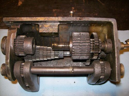
Inside, the QCGB isn't so simple.  We see the 'cone' of gears that allows subtle changes to the ratios - 8 to 10 to 12 etc.  On the right we see the gears which divide the spindle revolutions by two.  Each time the move the left lever, this side of the gearbox divides by 2, 4, or 8, etc..  If you look at the chart, you'll notice that the as you move down the chart, the numbers double.


The bad news is that I don't have a QCGB.  If I bought one, it would be quite a project to connect it to my lathe; my lathe was never made to have a QCGB.

What's a computer geek to do!

Perhaps I could just build the QCGB?  Nope - while it would be rewarding, the cost would be prohibitive.  There are probably 25 gears in there and they are very expensive.  Then there's everything else you see.  It adds up fast.

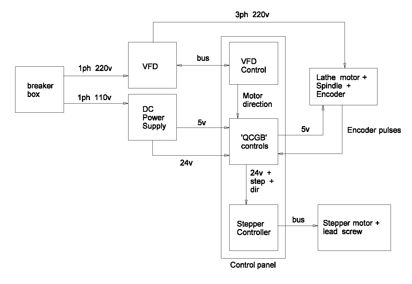
Perhaps I could 'CNC' the lathe - that is, control the carriage movement using a computer.  This requires a computer running dedicated machine control software to be connected to a motor that drives the lead screw.  There's a popular project on the internet called "electronic lead screw" that takes this approach.  I find it unconvincing.  Furthermore, I work with computers every day - I don't want one in the shop.  That's why I have a shop - to get away from computers!

My next idea was to build an electronically assisted QCGB.  Think cut-down CNC with a dedicated computer, tucked out of site.  But this is a lot like the Electronic Lead Screw project and is ultimately just an example of Not Invented Here.  Further, I've heard too many debates about processor speed, issues with non-related jobs running on the computer that induced lag (terrible) and so forth.

I decided to pare the design down to the bare minimum - an electronic device using typical 40xx chips - no programming, no processor, no operating system.  And, as an added benefit, raw speed.

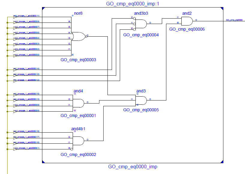
As I was researching the chips I'd need, however, I discovered something remarkable; an IC called a CPLD - Complex Programmable Logic Device.  In this simplest terms, this is a chip with a large number of gates that can be connected together pretty much arbitrarily.  Once connected, it's as if they'd been soldered together by hand.  These amazing devices can allow arbitrary designs tying together hundreds of gates. Best of all, the CPLD can be reprogrammed, thousands of times, using a USB cable and free software.  As if that wasn't enough, a small CPLD can be purchased for a princely $1.25.  The next size up, the one I need, costs $2.50.  I think I can handle it.

Ladies and gentlemen, we have a winner.

To learn about this technology, I purchased a development kit from Digilent that included the following board:


This board includes a pretty thumping CPLD (the Xilinx Coolrunner-II with 256 macrocells), 2 buttons, 2 slide switches, 4 LEDs, and a 4-digit 7-segment LED unit.  All you need to experiment and learn.  The dev kit comes with a USB cable for programming the CPLD and free development software.  So far, it's a 10/10.

Now my goal became clear - implement a full-featured QCGB using a CPLD.

(end of part 1)

In part 2, I'll talk more about the CPLD and what I'm doing with it.


Sunday, January 15, 2012

The Tool Bench, part 2.


Part 1 is here.

I intend to mount several stationary tools to the bench.  Since some are heavy and other will involve me applying some force, I decided to put a thick top on the bench.  After going through my scrap plywood pile, I found I had four pieces of 1/2" plywood that were all the right size.  The truth is, I had been using one of these for a temporary work surface.  When I sized the bench, I used the plywood's dimensions as a starting point and designed outwards.

The plan was to glue together these 4 sheets of plywood to make a heavy top.

The first step in gluing 4 sheets of plywood together is to get a friend to help.  My friend Marco came over to lend an assist.  We first taped plastic grocery bags over the sides and the lip on which the top would sit, so any squeeze-out would not glue the top to the sides.  We then numbered each piece of plywood so we could assemble the top in the correct order.  We discussed how the glue-up would happen. Carpenter's glue is made to set up pretty fast - this is usually a good thing.  For complex glue-ups, not so much!  We positioned all my clamps and cauls so when it was time, we'd be ready and wouldn't be fumbling for them.

Finally we placed the first sheet of plywood.  I got the first bottle of yellow carpenter's glue ready by removing the top.  I poured the glue right out of the bottle while Marco spread it over the plywood.  I poured about 8 ounces of glue - enough so the entire surface was wet and stayed wet.  Then we dropped the 2nd sheet of plywood in place and repeated the gluing procedure.  When all was said and done, I used a total of 32 ounces of glue.  I probably could have safely used more.

We verified that all the plywood was positioned correctly; it would be hard to fix after the glue set.  Then we clamped the plywood sheets down and together using bar clamps and cauls to spread the pressure evenly.  We used pairs of clamps and 2x4's on-edge to force the plywood sheets tight against the lip.  For better or for worse, the top now conforms to the bench.  It probably doesn't matter that much, the bench was pretty square.

The next day I took the clamps off.  Much to my relief, the plastic bags did indeed prevent us from gluing the top to the sides.  Had it not worked, there would have been little chance of ever getting the bench apart in case I had to get it out of the basement or perform some modification to it.

Here what the bench looks like with it's new 2" thick top.  Pardon my sawdust, I had to true up the edges of the top a little bit.


Here's a close up, though I don't know how helpful it is.


I had originally intended run some stringers around the bottom of the legs.  I don't know if I will or not.

Next steps will include screwing the top down and bolting down the tools.