Showing posts with label Craftsman. Show all posts

Tuesday, June 15, 2010

The Lathe Bench

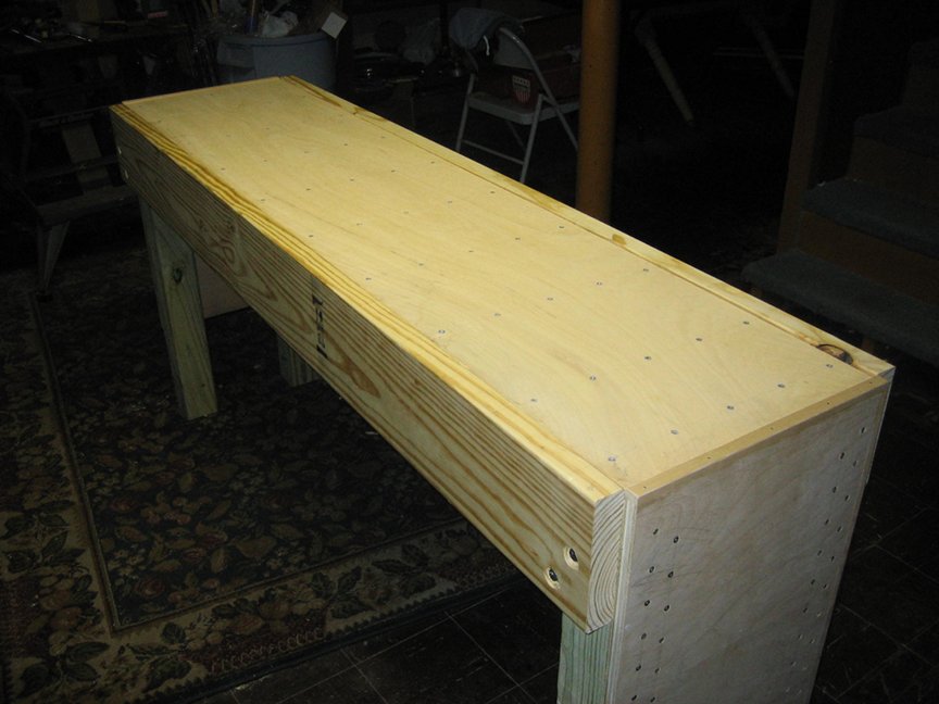
I didn't care for the stand my lathe was on. It was a skeleton made of angle iron. There was nowhere to place tools, no room for a chip tray, and it wobbled. I decided to build a proper bench.

This bench is about 19" x 72".

The surface is made of three sheets of 1/2" plywood, glued and screwed together, topped with a thin melamine-covered fiberboard sheet. The plywood wasn't the best choice but I already owned it - this material was stuff I had been tripping over in my shop.

The surface is resting on ten 2x4 'joists' spaced 8 inches on center. The joists are supported by 2x8 aprons. The 2x8s are bolted to 4x4 legs.

The ends are 3/4" plywood screwed and glued to the legs.

Here's an apron with it's joist hangers.


Because I could!


The other apron side is completed and the joists test-fitted.


Counter-bored holes for the lag screws. Note the flaw in the wood. I recommend you pay attention to these things.


Here a leg is attached to the apron. I clamped the leg against the apron, squared them, and bored two 1/4" holes through the apron into the leg. After that I opened the hole in the apron to 3/8" so the screw wouldn't split the wood. You can't really see it in these pictures but there's a washer below the lag screw heads.


The aprons and legs all together. The joists have also been attached to the hangers with a screw at each end. There's a good argument for putting a sheet of plywood under the apron to make sure it doesn't bow outward.


A great deal of the bench's strength comes from the plywood ends. I hate raw plywood edges. Invariably I ding them and raise a bunch of splinters. Then I impale myself. I covered up the top and front edges with a piece of 1/2" thick pine, glued and nailed.


I attached each plywood end piece to the legs using Liquid Nails and 44 screws. That's a lot of screws but they are functioning as clamps. Besides, I've had them for 15 years. Might as well use them. They are 'Robertson' screws from McFeely's. Highly recommended.


And here we are, both ends attached. The base of the bench is complete. If it shows any signs of lateral racking I'll add a piece of plywood or a diagonal support to the back.


My son and I dropped in the three 1/2" plywood top pieces, spreading Liquid Nails between them. I 'clamped' the plywood sheets together while the glue dried by driving 50 screws through them into the joists. I used some pretty old Philips-head deck screws for this. They cammed out terribly. I'm cured of Philips-head screws now.


Screws. Yah. I could have used fewer. I'm glad I didn't.


I found a piece of fiberboard with melamine on one side. I used double-side tape to secure it to the bench. The fiberboard was leftover from another project. I was delighted to have enough, even if I did have to use two pieces.


And here's the lathe on its new bench. I haven't decided for sure where the lathe is going to sit.


And that's the bench. It's sturdy and economical. I spend about $70 on it, excluding the plywood top and fiberboard.

Sunday, May 23, 2010

The Compound

While installing the toolpost on the lathe, I took the compound apart for the first time.

The compound is a part of the lathe that the tool holder sits on. It can swivel to allow a tool to present a more suitable cutting edge to the work. A screw mechanism allows the compound to be advanced and short tapers turned.

The compound is pretty simple. When the compound is swiveled, it is locked in place by 2 bolts. When tightened, they drive 2 angled steel pins into the hub on which the compound rotates. The pins lock the position by friction and draw the compound down against the carriage by their geometry.

Much to my horror, a previous owner had made an exciting enhancement. He had apparently lost the angled pins. Instead of making more, he turned points on two steel bolts. The points dug into the hub, gouging divots. The divots will prevent the compound from locking up at the right position, or may cause the compound to move unexpectedly. Horrible. I find it extra frustrating since it took only a few minutes to make replacement pins.

Here are the bolts that damaged the hub and the proper replacement pins I made.


I replaced these bolts with common hardware store bolts and turned a 'dog point' on each as per the originals.

Now a couple of pics of the hub showing the damage.


After getting a lot of good advice from the HSM on how to fix the hub, I won a far better casting on ebay for a very good price. That's good because I'm getting pretty tired of fixing abuse.

Thursday, April 29, 2010

Power and a new toolpost for the Lathe

I have been slowly restoring an abused Atlas/Craftsman 12" lathe to service. I've posted about the trials and tribulations over the last few years.

Recently I had an electrician install a new sub-panel for my basement shop. The electrician wired in a VFD, an amazing device that converts single phase power to 3-phase power. It lets me control almost anything related to the motor. For example, I configured the VFD so it starts the motor smoothly and will spin up to full speed in about 5 seconds. However, I configured it to stop the motor in 2 seconds. The VFD allows variable speed control without a loss of torque [1/27/13 - probably need a fact-check on this.] It also lets me reverse the motor. Good stuff. Further, the VFD supports a remote control panel so I can control the motor from the front of the lathe and not have to reach my hands in the sub-panel.

Here's the electrical work. The subpanel has breakers for outlets and the VFD. The white device is the VFD. It's about 4" x 4" x 6" and weighs nothing. The control pendant is sitting on the VFD's box. It has a potentiometer for the motor RPMs, an on/off toggle, and a forward/reverse toggle. Underneath the VFD's box, partially seen, is the 3-phase outlet for the motor.


Another advantage of 3-phase motors is that normal people don't want them. The nice Rockwell 1/2hp motor on my lathe was a Craigslist freebie. Gotta love that!

Here's the motor in all it's link-belt glory.


Moving on, the lathe's olde-school (circa 1936) lantern tool post has been "modified" and doesn't function properly. While it's fixable, I only have 2 of the special holders this tool post needs and they're expensive. So I replaced it entirely with a modern quick change tool post. It's a lovely thing. A quick change tool post set includes one toolpost and numerous holders. Cutting bits are secured in holders by Allen screws. The holders slide onto dovetails milled into the tool post and are locked in place when a lever is turned. It takes about 3 seconds to put a new tool in the tool post. Here's a picture of the new toolpost and an inaugural 5-foot long shaving.


Sunday, June 14, 2009

Replacing Atlas/Craftsman Part 9-11

The Atlas/Craftsman 12" metal lathe is a decent lathe for what it is - an entry level machine for the home shop hobbyist. This lathe was manufactured to meet a price point, not to be a professional quality lathe. One of the innovations employed in manufacture of this lathe was the use of a material called Zamak for many of the secondary parts such as change gears and handles. The idea was that die casting these parts from Zamak would save money and machining time. And it did.

Zamak, being an amalgam of zinc, aluminum, manganese, and copper is a reasonably durable alloy. It's stable, easy to cast, and plates well. Many common parts do very well when made of Zamac. But machines get bumped and banged. The Zamak parts broke much easier than their iron counterparts. When Atlas stopped making these lathes, inexpensive Zamak replacement parts largely disappeared too. Now the main assumption of Zamak - that replacement parts would be readily available and inexpensive - has become invalid. It's common to see Craftsman lathes will all manner of innovative replacements for broken Zamak parts. For example, when I bought my lathe the cross slide handwheel had been replaced with a water spigot knob.

But really, for the most part, the Zamak is ok. If a handle breaks after 70 years of use, well, you have a lathe, make another. There is one part, however, where the use of Zamak was downright egregious. And that is part 9-11, a housing that holds secure the pinion that connects the handwheel on the apron to rack. When you turn the handwheel, the carriage should move up and down the lathe bed. When part 9-11 breaks, and it will, parts fall out the bottom of the apron and your carriage gets all sad.

Here's a link to a document for my lathe. Refer to the "page 2" link - you can find part 9-11 at the bottom.

Here's a few images of part 9-11. This one doesn't fit my lathe, unfortunately. The lathe's original owner bought it without knowing that it fit a later model of the lathe.


The problem is this is a spindly part that gets a lot of lateral pressure applied to it. It never should have been made of Zamak, or at least not with this shape. The "legs" tend to break.

When I saw the part was missing, I checked Ebay, the easiest source for many Craftsman lathe parts. Since there is such a demand for 9-11 replacements the price is pretty high. I decided I would not pay top dollar for an antique Zamak part with a history of breaking. The only solution was to make a replacement.

Here's the diagram I worked from. All measurements are in decimal inches. Almost all measurements are multiples of 1/16". It was a simpler time.


The first image shows the bracket in place. There are three important things to note. First, notice the disruption of the aluminum where the axle passes through. That's because there is only a few mils of aluminum remaining there. Second, notice how the handwheel's small gear nestles in the angled area milled out of the bracket. Third, notice the poor fit of the large gear to the handwheel gear. The reason is in the notes below. Don't do what I did - I am still trying to remedy this.


Here's a view from the above front right, if it were in the apron. You can see the angled relief where the handwheel gear will fit.


Finally, here's a view from below. You can see the channel for the leadscrew.


Here are the instructions. The operations are all straight-forward. I had access to a mill. This would be hard to make otherwise.

  1. Acquire the large gear, small gear, and axle you see in the 9-11 pictures above. If you have a broken 9-11, you can salvage these. You will need to get one of the gears off the axle. Try an arbor press. On the 9-11 in the pictures above, the gears are peened on.
  2. Make the aluminum block. The width is extremely important. If it's too wide the gears will pinch the bracket when pressed on.
  3. Mark the location of the 1/2" hole. This is likely the most important measurement.
  4. Bore the 1/2" hole.
  5. Mill away the relief for the large gear. The depth must be at least the thickness of the large gear and the handwheel gear.
  6. Mill the "ears" through which the 1/4" bolts will pass. The depth of these was determined by the length of the bolts I had available. YMMV. You may not even need to add the ears at all if you use long bolts.
  7. Mill the leadscrew relief channel. When the channel intersects the axle hole you can stop. Removing more will not help.
  8. Put the axle in the bracket and carefully press the gears onto it. Check for a good fit before doing so. This will be hard to lubricate so add some über grease to the axle now. NOTE - the axle is NOT symmetrical. Be sure you orient it correctly.
  9. Put some layout blue on the bracket where it touches the apron, where the 1/4" bolts will pass. Put spacers between the mating gears so they will mesh correctly. Many people use paper scraps. Push the bracket firmly into position on the lathe. The gears on the bracket should engage the rack and the handwheel gear. Have a helper mark the bolt hole locations using a transfer punch.
  10. Bore the two holes for the 1/4" bolts.

Notes, in no particular order.
  1. I don't know how long this part will last. I am an amateur. Caveat Emptor.
  2. The part I am showing is a replacement for part 9-11 from an Atlas/Craftsman 12" lathe made in about 1937. It has no powered crossfeed and a 5/8" leadscrew. If your lathe if newer or different, you'll certainly have to make changes. If you have an identical lathe, you'll probably have to make changes :-D
  3. As far as I know, the design is correct. But you can probably find 100 improvements.
  4. I made mine from aluminum scrap. If you have iron or steel, all the better.
  5. The biggest mistake I made was drilling the 1/4" holes too soon. This should be the last thing you do. Drilling them last allows you to position the bracket on the lathe in exactly the right spot. I drilled my holes first and had the unenviable task of making sure both gears and both bolts all lined up. They didn't. So I got out a file... It was a big time-sucking mistake.
  6. When you prepare the part for the final fit, pushing it upward will make it engage the rack. Pushing it back and forth will make it engage and disengage the handwheel's gear.
  7. From the front view, you see the channel at the bottom. That channel is necessary for leadscrew clearance. It channel will just intersect the 1/2" hole you bored for the axle. Yes, the part is nearly cut in two. The Zamak part also has a divot out of the axle area. Anyway, if you can reduce the width of the channel, you'll strengthen the part. I didn't have the tooling.
  8. Most of the dimensions are non-critical. You need to get the 1/2" axle hole pretty close. The width of the part is also critical or the gears will pinch it or slide back and forth. The milled area must be deep enough to accommodate the large gear that attached to the axle.
  9. Go slow when you press the large and small gears onto the 1/2" axle. Mine fit great - I got lucky. It's possible that if your bracket isn't wide enough the gears will be pressed against the aluminum and turn very stiffly. To be avoided.

Saturday, October 13, 2007

My new lathe

I suppose the surest sign of getting old is buying a lathe. Especially a metal lathe. My lovely wife said, "And exactly what are you going to make with that? napkin rings? Candlesticks holders?" I was like, "I will probably use the lathe to make accessories for the lathe."

She just rolled her eyes and walked off.

So, I acquired a 1939 Craftsman 12" lathe, model 101.07383. It isn't a very popular lathe but it will do nicely for a while. The previous owner, Jim, was a remarkable man and a professional machinist. In his spare time he build and flew an aircraft. Around town, he was the guy you went to when you needed something fixed. He could tell you how to fix it or make the part you needed. Jim passed about 2 years ago.

I'm not really sure what happened to this lathe, but it is showing signs of being used and maybe abused. Most of the more ornate pieces are gone, replaced by more mundane parts. For example, a wheel on the apron has been replaced by an old water faucet handle! Perhaps this is what a working man's 70 year old lathe looks like.

My list of projects are:

1) Replace the motor, or repair the bearings.
2) Replace the counter shaft
3) Find out why the back gear shaft won't stay put.
4) Repair the carriage's traversal gear assembly

So once these are done, the lathe should be operational if not perfect.

Fortunately, I have access to a spare motor. #1 is handled for now.


Here's a picture. I'll get better ones up when the new basement shop isn't dungeon-dark.

I got the counter shaft off tonight. It isn't original and needs to be replaced. This should be cheap on ebay or easy to make. It isn't much more than a steel rod with two flats on it. I will have to learn how to replace bushings however.